Propeller makes it easy for you to use your local site calibration for your surveys. With a simple drag-and-drop, you can add your local calibration file from your survey software to your site in Propeller. It’s one of the reasons why worksite survey teams around the world choose Propeller every day.
Easy exports and imports
All of your drone data outputs (and your AeroPoint ground control points) will be available for download in your local site coordinates for use in your desktop workflows—so your Propeller data lines up with the data you already have.
Preexisting surveys and design information in your local site calibration can be uploaded and aligned with new surveys—so you can use and share all your information with Propeller’s powerful cloud tools.
Want to find out more about how local grid support works with drone surveys? Read on.
Why many sites use a local grid coordinate system
Many sites prefer to operate in a local coordinate reference system which measures positions on site relative to an arbitrarily placed point on the site. This can be for a number of reasons:
- It is sometimes beneficial to operate in ground coordinates rather than grid coordinates.
- The site’s coordinate system can be isolated from dynamically defined global geodetic systems, (such as WGS84, NAD83, GDA94) which are frequently revised due to shifting of the continents.
- The magnitude of site coordinates can be drastically smaller compared with state plane or national grid systems (which can extend into the millions of meters/feet), making them easier to work with.
These are known as local grids, or arbitrarily defined coordinate reference systems and they require some groundwork upon the establishment of the site in order to set them up.
How local grid systems are set up
Once a GPS base station is set up on a site, a surveyor can measure coordinates in a geodetic system (lat./long./elevation) using a rover. This system in which the base station operates, the local geodetic system, is close to, but not equal to the equivalent published system, for example, NAD83. This is consequent of some small uncertainty in the absolute global position of the base station—this is what constitutes the isolation of the site’s coordinate system from NAD83.
However, as long as the base station is placed on the same point, the rover can reliably measure coordinates in the local geodetic system. This is suitably accurate for most sites, as importance is not placed on global accuracy, rather repeatable accuracy within the site’s geographic bounds.
The next step is to define a suitable Cartesian, or local grid system, in which local geodetic coordinates can be expressed to make them more intuitive. This involves a surveyor creating a set of control points with an evenly distributed geometry across the extremities of the site and assigning them local grid coordinates, generally with the aid of a total station.
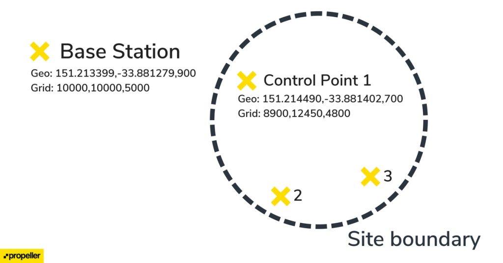
The final step is to determine the relationship between the local geodetic and local grid systems. This requires collection of a point pair on each control point. The point pair consists of local geodetic coordinates, collected from the rover’s observation, and corresponding local grid coordinates, manually entered into the rover from the point’s coordinates.
The rover itself or a computer software ingests these point pairs and uses them to generate a relationship between the two systems (a calibration file). Technically, this involves up to four operations:
- Geoid transformation: this reduces geoid-based height to ellipsoid heights.
- Geodetic datum transformation: this converts local geodetic coordinates to an arbitrarily defined geodetic system.
- Projection: this converts geodetic coordinates to an arbitrarily defined projected system.
- Calibration: this step ‘shifts’ the projected coordinates into local grid coordinates by means of applying a similarity transform in both the horizontal and vertical axes.
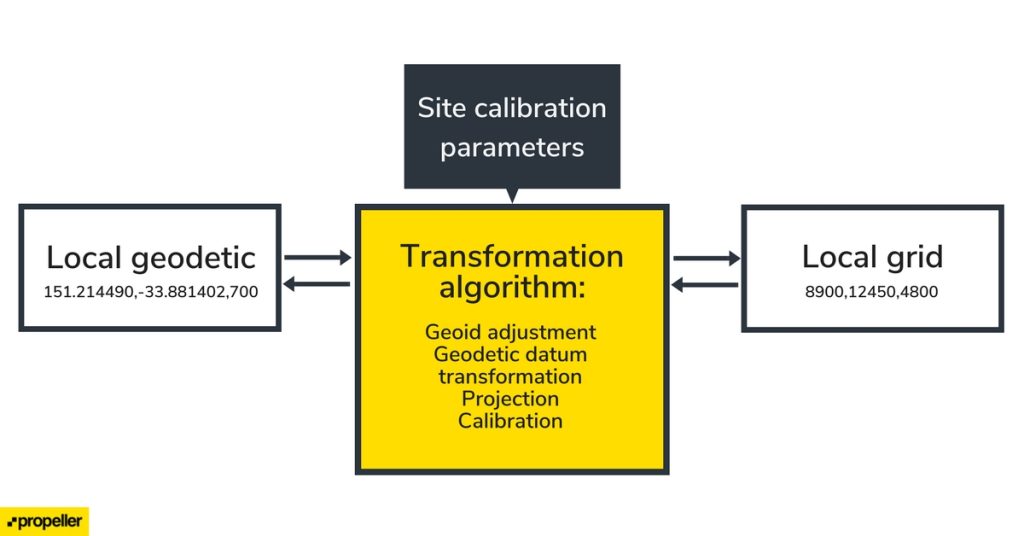
These combined operations provision conversion between the local geodetic and local grid systems, and this is what Propeller utilizes in order to process and deliver data in your custom coordinate reference system.
Determining if your site has a local coordinate system
Most sites use Cartesian systems to measure ground coordinates. If your coordinate system is referenced by a code from the EPSG, ESRI, or FIPS authorities, describing a national grid or state plane, then this is a published system and not a local grid system. Propeller can process data in most of these systems without additional information.
If not, then we require information about your local site calibration in order to process and deliver data in this system. We refer to the file containing this information as a calibration file. These files are generated by a rover or surveying software suite and describe the parameters required to transform coordinates between a site’s local geodetic and local grid systems.
How Propeller handles local grid coordinates
If your site uses a local grid system, we require a calibration file to be uploaded before drone imagery or AeroPoints data is submitted for processing.
Creating a new site and configuring your local coordinate system
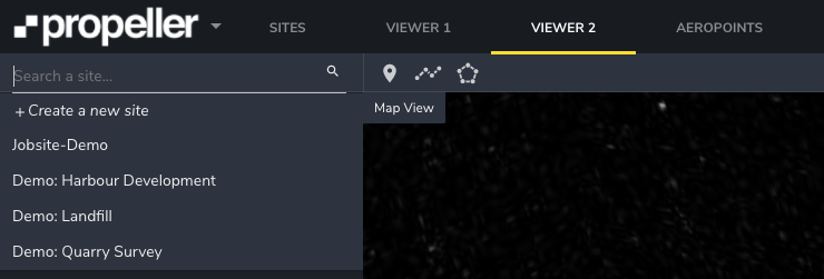
Propeller is rolling out support for the direct upload of calibration files from within ‘Create a new Site’ window. This can be accessed by clicking on Create a new site in Viewer 2:
Once you have entered a site name and clicked save, you will see the configure local grid option.
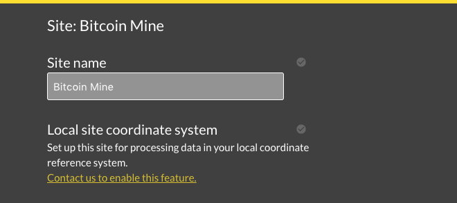
Please note that this option is enabled by default on Propeller’s new pricing plans. If you are using one of our older plans and you don’t see this option, contact us to discuss an upgrade.
Clicking through will take you to the calibration file submission page.
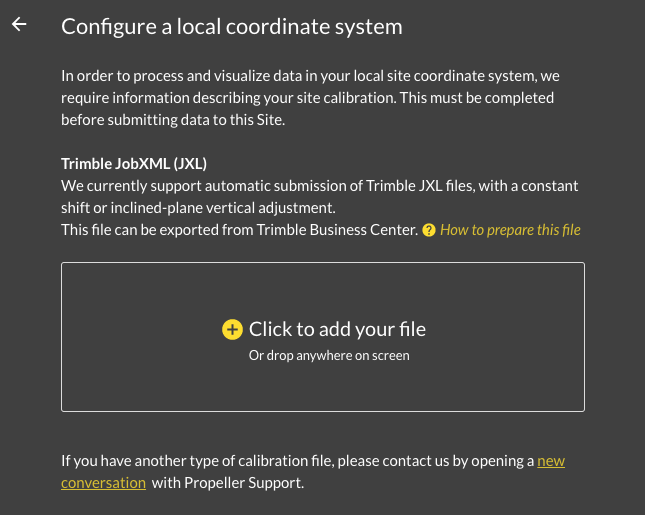
If you have a calibration file of a format that we currently accept (see Current status below), then it will be processed automatically. Otherwise, please contact our support team and we will assist you in getting your site set up.
You will then be ready to submit data to your newly created site.
Uploading your data for processing
Survey data
Uploading survey data for processing on a local grid calibrated site requires submission of ground control points such that we are able to generate outputs in your local grid system. If you use your own GCPs, their coordinates must be expressed in the local grid system, which will be prompted by our data uploader:

If you use AeroPoints, check Using AeroPoints with local grid calibrated sites below.
- Preprocessed data (BYOD plans)
- We currently accept TIFF files georeferenced in a published system (non-local). These files will be processed into your local system for visualization.
- Design surface data
- We currently accept TIFF files georeferenced in a published system (nonlocal) and Trimble TTM files for local processing.
- Inspection data
- Data submitted as an inspection currently can not be processed in your local system.
Please note that Local Coordinate Systems and Local Site Survey Benchmark processing options are only supported when processing data sets using AeroPoints with the Propeller or Stratus platforms. If you would like more information, please contact us.
Visualizing and downloading local grid data
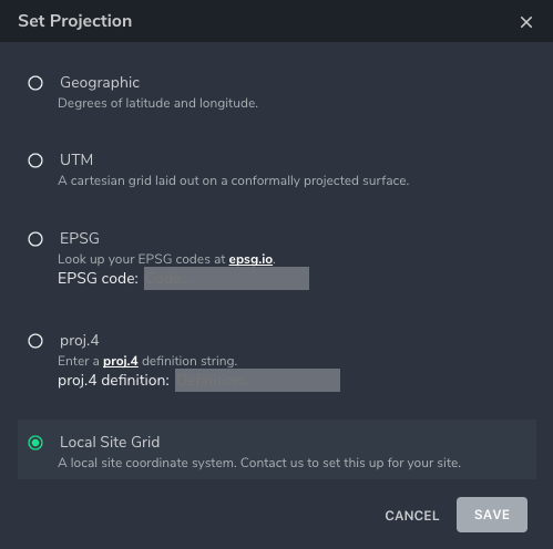
Once processing has completed, outputs will be available on the Propeller Platform for visualization, measurements and download both in the site’s local geodetic (~WGS84) and local grid systems. You can switch between this two options in the Projection menu of the settings dropdown.
Using AeroPoints with local grid calibrated sites
A site calibration defines a transform between local geodetic and local grid systems.
AeroPoint surveys processed with the Propeller Correction Network (CORS-based) yield coordinates in a third system, global geodetic, which cannot be assumed to be equivalent to local geodetic. Therefore it is not advised to use the Propeller Correction Network method for AeroPoint surveys on a local grid calibrated site.
The solution is to use the Local Site Survey Benchmark processing method, wherein you provide the surveyed local grid coordinates of one of the AeroPoints from the set. All other AeroPoints in the survey are then corrected against this point, ensuring that resultant coordinates are conformal to the site’s local geodetic / local grid systems which we use to process your data.
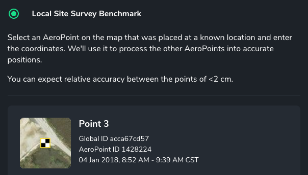
Once you have submitted your AeroPoints for processing, you can submit them as GCPs in the upload flow.
Current status
Jan. 2018
- Released support for calibrations with an inclined-plane vertical calibration. If your site calibration uses a geoid, we require it to be recalculated using an inclined plane.
- Self-service submission of Trimble JobXML (.jxl) calibration files through the Create new Site flow. If you have a different type of calibration file, please contact our Support Team.


